A non-grid exposure is made using 70 kVp 25 mAs and 6 IWKHHSRVXUHZHUHWREHUHSHDWHGZLWKD grid what technique would be required. During computer processing image brightness is maintained when the mAs is too low or too high.

Conventional Average Radiation Parameters Kvp Mas From Different Download Table
The working ability of a grid is described by the grid ratio which is the ratio of the height of the lead strips h to the distance between two strips ie.
Adjustment of kvp and mas using grid ratio. DIGITAL OPTIMUM kVp Universal CR Technique Chart using a standard 21 LgM Part View kV mAs kV mAs kV mAs Abdomen AP Grid 85 10 -15 85 20 - 25 85 30 - 40 Ankle AP 70 18 70 2 70 25 Ankle Obl 70 16 70 18 70 22 Ankle Lat 70 15 70 16 70 2 Chest -Adult AP 400 - tt -72 85 2 - 25 85 32 - 4 90 5 - 64. The addition of a grid will help clean up the scatter radiation produced by higher kVp but it requires an mAs adjustment. It works for most radiographic situations.
Grid ratio is defined as. Maintaining or adjusting exposure to the IR can be accomplished with kVp by using the 15 rule. The choice to use a grid depends on.
4 - Higher grid ratios are _____ efficient in reducing secondaryscattered radiation reaching the film and are _____ when using high kVp. These studies used mean. This is like a grid.
Every cm increase of patient thickness requires a 25 increase in mAs. The adjustment in technical factors required when using beam restriction is. Instead of adjusting kVp and mAs around a constant detector exposure these studies investigated the concept of lowering kVp and increasing mAs to achieve a constant patient dose but with an increase in contrast-to-noise ratio CNR1920 The detector exposure decreases in this scenario resulting in a lower exposure index EI.
For example increasing the kVp from 82 to 94 15 produces the same exposure to the IR as increasing the mAs from 10 to 20. Exact adjustment varies a few percent which has a negligible effect on image quality. 52 kVp 32 mAs small focal spot.
This rule comes from the fact that 115 5 20. Same effect as mAs on the image quantity Under penetration noise. Double density- increase kVp by 15.
D because it has the lowest grid ratio and is the least efficient. If the exposure is to be repeated using a 121 what mAs is required. Every cm increase of patient thickness requires a 25 increase in mAs.
APOblq Knee Grid mAs CM kVp Yes 113 7-8 66 150 11-12 70 15-16 70 44 150 9-10 66 225 13-14 7017-18 Lateral Knee Decrease 4 kVp Decrease 4 kVp Decrease 4 kVp LOWER LEG APLateral Grid mAs CM kVp N 30 5-6 66 40 9-10 70 13-14 74 44 40 7-8 66 60 11-12 70 15-16 74 FOOTANKLE Ankle Grid mAsCM kVp mAs CM kVp CM kVp APOblq N 1 5-6 56 10 7-8 60 11. Thus if the kVp is increased by 15 then the mA must be decreased by a factor of 2 in order to maintain constant exposure on the image receptor. 50 MaS is used with a part size of 26 cm.
If kVp values fall below the lowest available kVp setting then adjust the low kVp values upward while decreasing the mAs values to compensate. When a nongrid technique using 10 mAs and 75 kVp is changed to a 121 grid using 75 kVp what new mAs must be used to maintain the same density as the original. Keep same densityIR exposure Original mAs24.
Use higher kVp and lower mAs in digital because control contrast during computer processing. Therefore for each increase of 15 in kVp the exposure will double. No grid 1 the original mAs 51 grid 2 the original mAs.
Less scatter on film but less detail also. Direct but not proportional relationship with density. The level of mAs does not directly affect image brightness when using DIGITAL IRs.
15 MaS is used with a part size of 13 cm. The ability to reduce mAs by a fifth-power relation is more than adequate to balance the second to third power direct effect of increasing kVp on photon quantity. The ratio of the lead strips to the space between them.
Maintaining or adjusting exposure to the IR can be accomplished with kVp by using the 15 rule. 20 MaS is used for a part size of 22 cm. 72 KVP is used for a part size of 16 cm.
An 81 grid is used with 10 mAs and produces sufficient exposure. The 15 rule states that changing the kVp by 15 has the same effect as doubling the mAs or reducing the mAs by 50. - What are the most common grid ratios.
Over penetrationincrease in pt dose. Although one can alter the kVp the usual method of adjustment is to change the mAs which is dependent on the grid ratio. For example increasing the kVp from 82 to 94 15 produces the same exposure to the IR as increasing the mAs from 10 to 20.
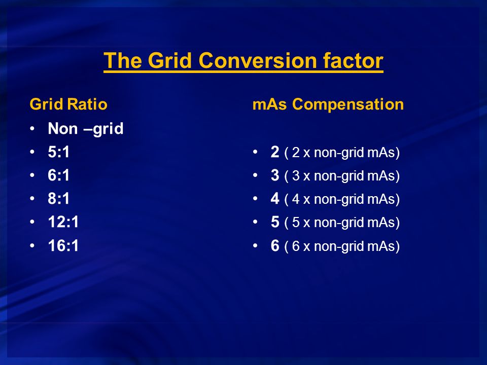
1 KVP used 2 thickness of part Parts 10 cm or larger with a KVP higher than 60 produce enough scatter to necessitate the use of a grid. A lower-than-needed mAs produces an image with increased quantum noise and a higher-than-needed mAs exposes a patient to unnecessary radiation. One of the easiest methods used to calculate the change in technique required by the addition of a grid or by changing from one grid ratio to another is to assign a correction factor value to each grid as follows.
Wireless detector placed on a rollaway holder. Grid efficiency - Grid ratio - The relationship of the height of the lead strips to the _____ of the interspace material between them. As the fifth-power rule of thumb goes 7 to maintain the same image receptor exposure every 15 change in kVp should be accompanied by an inverse adjustment in mAs by a factor of 2.
It works for most radiographic situations. Adjust the KVP for a part size measuring 19 cm. 1 Increases contrast 2 Reduces density 3 Must use more MAS with a grid.
Note that there is a dramatic increase of image quality achieved by removal of most of the scatter radiation and well worth the cost in additional radiation dose to the patient. Exact adjustment varies a few percent which has a negligible effect on image quality. Adjust the MAS for a part size measuring 30 cm.
Adjust the MaS for a part size measuring 15 cm. Model is in a right lateral position next to direct radiography detector with the grid removed from the upright Bucky. KVp and Digital Imaging.
A grid ratio of 81 is generally used for 70-90 kVp technique and 121 is used for 90 kVp technique. Use the 15 rule to find the new kVp with the change in mAs goal. Wireless detector in position for an x-table digital image of the left lateral nasal bone.
According to the grid conversion factors listed here the addition of an 81 grid requires that the original mAs be multiplied by a factor of 4. The 15 rule states that changing the kVp by 15 has the same effect as doubling the mAs or reducing the mAs by 50. No grid was used for 5070 kVp and a grid used for 70117 kVp SID 100 cm.
Description of the systems 1. SID 100 cm. Description of the systems 1.
The Bucky factor is thus 8 ie 25 mAs3 mAs and this is a quantitative measure of the increase in patient dose resulting from the use of the scatter removal grid. A knee is obtained using a 161 ratio grid at 65 kVp and 12 mAs. 80 kVp 15 92kVp.
No grid was used for 5070 kVp and a grid used for 70117 kVp. If some exposure times are excessively long and you are already using the highest available mA setting lower exposure times can be achieved by selecting a faster receptor speed using a lower ratio grid and by reducing the anode-film. Adjust the MaS for a part size measuring 20 cm.
A80 kVp 125 mAs 40 inch SID 161 grid b80 kVp 100 mAs 40 inch SID 121 grid c80 kVp 75 mAs 40 inch SID 81 grid d80 kVp 50 mAs 40 inch SID 51 grid Which will produce the longest scale of contrast.

X Ray Scatter Collimation Kvp Air Gap Thickness Anti Scatter Grids Factors Every Technologist Should Know How Radiology Works


Tidak ada komentar